
Wingpath has ceased trading
We are no longer selling licences for our software products (ModSnmp, ModMultiSim, Modsak, ModSlaveSim, ModMaster and ModTest).
The website will remain operational until at least 2027 for reference purposes, and for the registration and transfer of product licences.
ModMultiSim help v3.07 - 4.3.7. Gas blender
Download manual: HTML
This example simulates a gas blender. The blender has three gases flowing into it through separate inlet pipes. These pipes join to form the outlet pipe, which supplies the blended gas.
Each inlet pipe is fitted a with a flow rate sensor and a valve to vary the flow rate.
The outlet pipe is fitted with a pressure sensor. This is used to monitor demand for the blended gas, since increased demand will tend to reduce the outlet pressure.
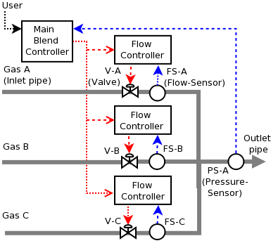
The main controller (slave 1) tries to maintain the required proportions of each gas in the blended output, and also to maintain the required outlet pressure. The main controller is aided in this task by flow controllers (slaves 2, 3 and 4) on each of the inlet pipes.
Note that this example uses mass flow rates (or standardized volume flow rates), not volume flow rates.
GUIDE:
(To load this simulation select the file Gas blender from File->Simulation Examples....)
When ready to start press Run Slave Simulation. Press it again to stop or pause the simulation.
Click the tab for slave 1, the main controller. To view the relevant values as they change, you might want to lengthen the window and move the horizontal divider bar up to give more space to the Environment table (or you can simply scroll the Environment table to see the values). After you start a simulation, remember you can pause it frequently in order to find a register value you have been directed to.
When you first run the simulation. you will see that the controlled variables (gas percentages and outlet pressure) are close to their respective target values (or set points): target values are registers 0-3 in slave 1's register table (0:PressureSP, 1:A PerCentSP ...), which can be compared with the actual values in the Environment table (APerCent, BPerCent, CPerCent and OutletPressure).
Now pause the simulation. To see the main controller in action maintaining a blend with the required proportions of each gas, you can adjust the inlet pressure of a gas to reduce the corresponding flow rate of that gas: in the Environment table, enter 65 as the value for APressure (and press Enter). Look in the Environment table to see changes in the following values after you restart the simulation (remember you can pause the simulation in between looking at each of the values below:
- AFlowRate. the flow rate for Gas A drops suddenly immediately after the restart.
- AValveOpen. The value gradually rises - the valve on the inlet pipe for Gas A is slowly being opened by the main controller..
- APerCent. The proportion of gas A is also now below the required level set in slave 1's 1:APerCentSP, but likewise gradually rises.
- BPerCent, CPerCemt, Each of the other component gases are also affected with their flow rates and percentages increasing initially to compensate for the reduced flow from Controller A, but as the main controller adjusts their valves, their flow rates and gas percentages each return close to their corresponding set points: in slave 1's 2:BPerCentSP, 3CPerCentSP, They do not exactly reach the setpoints due to the imprecision of floating point arithmetic.
Pause the simulation again and reset the Environment variable APressure back to 70 . Now try increasing the demand for gas: set Demand in the Environment table to 12. Things to notice when you restart the simulation are that the outlet pressure (OutletPressure in the Environment table) initially falls and then recovers as the main controller increases the flow rate to compensate (see slave 1's 4:Flow Rate). Notice too how the controller maintains the gas percentages close to their setpoints while the pressure is being restored.
Pause the simulation once more. You could also try changing the blend, for example, set the target proportion of gas B to 25 (set in slave 1's register 2:BPerCentSP) and watch the controller adjust the flow rates to produce the new blend. In the Environment table, you will see BFlowRate increasing and CFlowRate decreasing. Notice again how the outlet pressure is maintained close to its setpoint while the blend is being adjusted.
For further guidelines see Running Example Simulations
The program listing and explanatory notes for the simulation follow. Before looking at them, please read the short sections Introduction to programming simulations and Language: Quick Start Guide
The table below show the simple program underlying the simulation of the environment, which includes the demand for gas, the status of valves, and the gas flow rates and pressures.
Table 12. Environment: pressures, flow rates and valves
| Property Name | Statement |
|---|---|
| Demand | |
| OutletFlowRate |
$AFlowRate + $BFlowRate + $CFlowrate
|
| OutletPressure |
$$ + ($OutletFlowRate - $$ * $Demand) * CycleTime / 105.0
|
| AFlowRate |
($APressure - $OutletPressure) * AValveOpen * 0.15
|
| AFlowRateSP |
$1$5
|
| APerCent |
$AFlowRate / $OutletFlowRate * 100
|
| APressure | |
| AValveOpen |
if $2$0 < 0 then 0 else if $2$0 > 100 then 100 else $2$0 |
| BFlowRate |
($BPressure - $OutletPressure) * BValveOpen * 0.15
|
| BFlowRateSP |
$1$6
|
| BPerCent |
$BFlowRate / $OutletFlowRate * 100
|
| BPressure | |
| BValveOpen |
if $3$0 < 0 then 0 else if $3$0 > 100 then 100 else $3$0 |
| CFlowRate |
($CPressure - $OutletPressure) * CValveOpen * 0.15
|
| CFlowRateSP |
$1$7
|
| CPerCent |
$CFlowRate / $OutletFlowRate * 100
|
| CPressure | |
| CValveOpen |
if $4$0 < 0 then 0 else if $4$0 > 100 then 100 else $4$0 |
Notes
Demand. The demand for the blended gas. (This is modelled as the "conductance" of the supplied system - the higher the conductance, the lower the resistance of the supplied system to the gas flowing into it.) The demand is set manually in this simulation, but could have been varied using, for example, a random walk.
-
OutletFlowRate. The rate at which the blended gas is flowing out of the blender. This is the sum of the flow rates of the individual gases.
$AFlowRate + $BFLowRate + $CFlowRate -
OutletPressure. The gas leaving the system is assumed to be temporarily stored (even if it is only in the outlet pipe itself). The change in pressure in this storage is proportional to the rate at which gas flows into the storage (OutletFlowRate) minus the rate at which it flows out (OutletPressure * Demand). The constant 105.0 is a measure of how quickly the pressure changes for a given net flow rate. (in electrical terminology this would be the capacitance of the storage).
$$ + ($OutletFlowRate - $$ * $Demand) * CycleTime / 105.0 -
AFlowRate, BFlowRate, CFlowRate. The actual flow rate of each gas. To keep the simulation simple, the flow rate is assumed to be proportional to the valve opening multiplied by the pressure difference across the valve. For example, as in the statement for the AFlowRate register:
($APressure - $OutletPressure) * AValveOpen * 0.15 AFlowRateSP, BFlowRateSP, CFlowRateSP. The required flow rate of each gas, as specified by the main controller ($1:$5: A Flow Rate SP, $1:$6: B Flow Rate SP and $1:$7: C Flow Rate SP). These are used by the respective flow controllers (slaves 2, 3 and 4).
-
APerCent, BPerCent, CPerCent. The actual percentage of each gas in the blended output. These are not used by any of the controllers - they are just for monitoring the simulation. Here is the statement for the APerCent register:
$AFlowRate / $OutletFlowRate * 100 APressure, BPressure, CPressure. The inlet pressure of each gas. These are set manually in this simulation, but could have been varied using, for example, random walks.
-
AValveOpen, BValveOpen, CValveOpen. The opening of each valve, as a percentage. These are set by the respective flow controllers ($2:$0: Valve Open, $3:$0: Valve Open and $4:$0: Valve Open). The statements limit the range to 0..100, as the controllers may output values outside this range. For example, the valve opening of inlet pipe A is controlled by slave 2 register 0 ($2$0) in the following statement for AValveOpen:
if $2$0 < 0 then 0 else if $2$0 > 100 then 100 else $2$0
The table below show the simple program underlying the simulation of the slave responsible for controlling the flow of gas A.
Table 13. Slave 2: gas A flow controller
| Register Address | Register Name | Statement |
|---|---|---|
| $0 | Valve Open |
$$ + 0.039 * (($AFlowRateSP - $AFlowRate) - $1 + 0.3 * CycleTime * ($AFlowRateSP - $AFlowRate)) |
| $1 | PrevError |
$AFlowRateSP - $AFlowRate
|
Notes
-
$0: Valve Open. Controller output to the valve, specifying how open it should be (as a percentage). The statement for this register adjusts the valve opening to minimize the error '
$AFlowRateSP - $AFlowRate', i.e. to keep the flow rate of gas A (AFlowRate) as close as possible to the setpoint (AFlowRateSP) set by the main controller.This register (together with $1: PrevError) is a PI controller (using the velocity algorithm template), with a controller gain Kc of 0.039, and an integrating constant Ki of 0.3. in the statement for $0: Valve Open:
(CO)        $0:	$$ +
		0.039 * (($AFlowRateSP - $AFlowRate) - $1 +
		0.3 * CycleTime * ($AFlowRateSP -$AFlowRate))
(PrevError) $1:	$AFlowRateSP - $AFlowRate
The labels for the registers correspond to their role in the template. The calculation for the valve adjustment is the italicized code, which is done separately in CO increment in the template. Also, to simplify the simulation, the increment is always added to the current value of Valve Open, rather than keeping Valve Open between upper and lower limits.
$1: PrevError. The error on the previous cycle, for use by the PI controller.
The controllers for gas B (slave 3) and gas C (slave 4) are similar.
The table below show the simple program underlying the simulation of the main controller, which is responsible for maintaining the required outlet pressure and blend of gas.
Table 14. Slave 1: main controller
| Register Address | Register Name | Statement |
|---|---|---|
| $0 | Pressure SP | |
| $1 | A PerCent SP | |
| $2 | B PerCent SP | |
| $3 | C PerCent SP | 100.0 - $1 - $2 |
| $4 | Flow Rate |
$$ + 26 * (($0 - $OutletPressure) - $8 + 0.04 * CycleTime * ($0 - $OutletPressure)) |
| $5 | A Flow Rate SP | $4 * $1 / 100 |
| $6 | B Flow Rate SP | $4 * $2 / 100 |
| $7 | C Flow Rate SP | $4 * $3 / 100 |
| $8 | PrevError | $0 - $OutletPressure |
Notes
$0: Pressure SP. The required outlet pressure.
$1: A PerCent SP, $2: B PerCent SP, $3: C PerCent SP. The required percentages of each gas in the blended output. The percentage for gas C is set from the percentages of the other two gases, to ensure that the total is always 100%.
-
$4: Flow Rate. The main controller output, specifying what the flow rate of the blended gas should be. This is split into separate outputs for each gas in registers A Flow Rate SP, B Flow Rate SP and C Flow Rate SP.
The statement for this register adjusts the flow rate to minimize the error '
$0 - $OutletPressure', i.e. to keep the outlet pressure (OutletPressure) as close as possible to the setpoint ($0: Pressure SP) set by the operator.This register (together with $8: PrevError) is a PI controller (using the velocity algorithm), with a controller gain Kc of 26 and an integrating constant Ki of 0.04 in the statement for $4: Flow Rate:
(CO)        $4:	$$ +
		26 * (($0 - $OutletPressure) - $8 +
		0.04 * CycleTime * ($0 - $OutletPressure))
(PrevError) $8:	$0 - $OutletPressure
The labels for the registers correspond to their role in the template. The calculation of the flow adjustment is the italicized code, which is done separately in CO increment in the template. Also, to simplify the simulation, the increment is always added to the current value of the flow rate, rather than keeping the flow rate between upper and lower limits.
-
$5: A Flow Rate SP, $6: B Flow rate SP, $7: C Flow rate. The flow rates specified by the controller for each gas. Each flow rate is calculated by multiplying the total flow rate ($4: Flow Rate) by the required precentage for that gas ($1: A Percent SP, $2: B Percent SP or $3: C Percent SP).
These required flow rates are routed via the environment properties AFlowRateSP, BFlowRateSP and CFlowRateSP to the respective flow controllers (slaves 2, 3, and 4).
$8: PrevError. The error on the previous cycle, for use by the PI controller ($4: Flow Rate).