
Wingpath has ceased trading
We are no longer selling licences for our software products (ModSnmp, ModMultiSim, Modsak, ModSlaveSim, ModMaster and ModTest).
The website will remain operational until at least 2027 for reference purposes, and for the registration and transfer of product licences.
ModMultiSim help v3.07 - 4.3.6. Lift pump station
Download manual: HTML
This example simulates a lift pump station. The station has a tank that is continuously being filled with drainage water, and two pumps (pump A and pump B) that are used to pump water out of the tank and keep the water level within required limits.
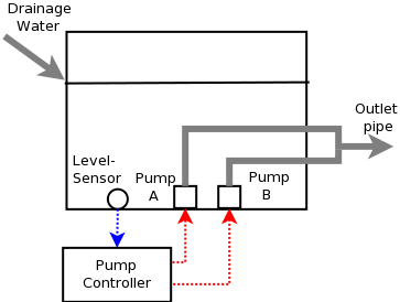
Each pump operates at a fixed rate, but either or both pumps may be started in order to provide some control of the pumping rate. One pump (the "lead pump") is started when the water reaches a specified level, and the other pump (the "lag pump") is started when a higher specified level is reached. When the water level drops, the pumps are stopped in reverse order - i.e.lag pump pump is stopped first. (see Registers 2-5 - e.g. StartLagSP is the water level set point (SP) for the lag pump.) The stop levels would normally be set lower than the start levels to provide some hysteresis.
If the same pump was always used as the lead pump, it would wear more quickly than the other pump. To even out the pump wear, the lead/lag roles of the pumps are switched when the lead pump has been running for a specified period longer than the lag pump (indicated by whether PumpARunning or PumpBRunning has a value of 1).
The starting of each pump can be delayed for a specified period. (registers 7-8). This can be used to avoid the pumps starting at the same time after a power failure.
This example also simulates manual override of the pump control, and failure of either or both of the pumps.
GUIDE:
(To load this simulation select the file Lift pump station from File->Simulation Examples....)
When ready to start press Run Slave Simulation. Press it again to stop or pause the simulation.
Notice when you run the simulation that initially pump A is running (PumpARunning is 1), pump B is not running (PumpBRunning is 0), and the water level is rising (see WaterLevel in the Environment and the monitored level $0:Level). When the water level reaches 7ft (or $0:Level reaches 70 (1/10ths ft)), the trigger point stored in register $2:startLagSP, Pump B is started and the water level starts to fall. (However, you will see a delay after the level is reached before pump B starts, which is the 8 second delay required by register $8:StartLagDelay.) When the water level has fallen to 3 feet (register $0:Level is 30), which is the level at which the lag pump should stop (see $4:StopLagSP), pump B is stopped, and the water level starts to rise again.
Try reducing the FillRate to 0.15 and notice that the water level is now controlled by starting and stopping the lead pump, without needing a second lag pump. The lead pump is initially pump A.
If you leave the simulation running for several minutes you will see the roles of pump A and pump B being switched ($21:PumpALead changes between 1 and 0), to even out wear and tear on a pump. In this simulation the pumps are switched when the current lead pump has been running 180 seconds longer than the current lag pump. For example, if $28:PumpATime exceeds $29:PumpBTime by the value in $30:AltTime, then pump B will become the lead pump.
If the fill rate is increased to 0.5, note that the water level continues to rise even with both pumps in operation, and when the level in $0:Level reaches 90, the trigger point stored in register $1:AlarmHighSP, then an alarm is raised ($22:AlarmHigh is set to 1), .
For further guidelines see Running Example Simulations
The program listing and explanatory notes for the simulation follow. Before looking at them, please read the short sections Introduction to programming simulations and Language: Quick Start Guide
The table below shows the simple program underlying the simulation of the environment, which includes the status of the pumps, the rate at which drainage water flows into the tank, and the water level in the tank.
Table 10. Environment: tank level and pumps
| Property Name | Statement |
|---|---|
| FillRate | |
| PumpAFailed | |
| PumpARate |
if $PumpARunning == 1 then 0.2 else 0
|
| PumpARunning |
if $PumpAFailed == 0 && $1$26 == 1 then 1 else 0
|
| PumpBFailed | |
| PumpBRate |
if $PumpBRunning == 1 then 0.2 else 0
|
| PumpBRunning |
if $PumpBFailed == 0 && $1$27 == 1 then 1 else 0
|
| WaterLevel |
$$ + ( -$PumpARate - $PumpBRate + $FillRate) * CycleTime
|
Notes
FillRate. The rate at which drainage water is flowing into the tank. For simplicity in this example, the rate is expressed as the rate of change in water level (in units of feet/second). It is set manually in this simulation, but could have been varied using, for example, a random walk.
PumpAFailed, PumpBFailed. These may be set to 1 to simulate a pump failure.
PumpARate, PumpBRate. The rate at which each pump is pumping water. If the pump is not running then the rate is 0, otherwise the rate is a constant 0.2. For simplicity in this example, the rate is expressed as the rate of change in water level (in units of feet/second).
PumpARunning, PumpBRunning. Whether each pump is running. A pump is running if it has not failed and it has been commanded to run by the controller (via $1$26: Pump A Run or $1$27: Pump B Run).
-
Water level. The water level in the tank, measured in feet. The water level changes at a rate that is the difference between the rate at which drainage water flows into the tank and the rate at which the pumps pump it out.
This simulation of the water level illustrates how one can use simple concepts in modelling the environment but nevertheless produce a simulation capable of testing a master.
NB: The simulation can also be related to the differential equation in an integrating first-order model. For those interested in the mathematical model and its correspondence to this simulation, read the following paragraph and see integrating first-order model.
-
Since the simulation is fairly simple, much of the detail from the model is implicit. For example, examine the correspondence between the model template (listed first) below and the $WaterLevel register (controlled variable $CV) (listed second). Here the $FillRate is the disturbance $D:
1.$$+($Ks *$CO 		      + ($Kd *$D))  *CycleTime/$Ts
2.$$+(-$PumpARate- $PumpBRate + ($FillRate))*CycleTime
$PumpARate (and $PumpBRate) is the rate of pumping water and implicitly expresses the 'pump's power over resistance' ($Ks in the template), when the pump is running (times $CO in the template), (which is explicit within the statement for $PumpARate). Likewise $FillRate expresses how much the water level changes when the fill rate changes ($Kd * $D), which in a more detailed simulation might include the volume of the tank, pipes, water level. How quickly the water level changes as the pump rate and fill rate change ($Ts) is implicit here with a value of 1.
-
The table below shows the simple program underlying the simulation of the slave, which controls the operation of the pumps and thereby controls the level of water in the tank.
Table 11. Slave 1: pump controller
| Register Address | Register Name | Statement |
|---|---|---|
| $0 | Level | $WaterLevel * 10 |
| $1 | Alarm High SP | |
| $2 | Start Lag SP | |
| $3 | Start Lead SP | |
| $4 | Stop Lag SP | |
| $5 | Stop Lead SP | |
| $6 | Alarm Low SP | |
| $7 | Start Lead Delay | |
| $8 | Start Lag Delay | |
| $9 | Pump A Mode | |
| $10 | Pump B Mode | |
| $11 | Lead On Time |
if $0 < $3 then TimeNow
|
| $12 | Lag On Time |
if $0 < $2 then TimeNow
|
| $20 | Alt Manual | |
| $21 | Pump A Lead |
if $PumpAFailed == 1 then 0 else if $PumpBFailed == 1 then 1 else if $28 > $29 + $30 then 0 else if $29 > $28 + $30 then 1 |
| $22 | Alarm High |
if $0 >= $1 then 1 else 0
|
| $23 | Alarm Low |
if $0 < $6 then 1 else 0
|
| $24 | Lead Run |
if $0 >= $3 && TimeNow > $11 + $7 then 1 else if $0 < $5 then 0 |
| $25 | Lag Run |
if $0 >= $2 && TimeNow > $12 + $8 then 1 else if $0 < $4 then 0 |
| $26 | Pump A Run |
if $9 == 1 then 1 else if $9 == 2 then 0 else if $21 == 1 then $24 else $25 |
| $27 | Pump B Run |
if $10 == 1 then 1 else if $10 == 2 then 0 else if $21 == 1 then $25 else $24 |
| $28 | Pump A Time |
if $PumpARunning == 1 then $$ + CycleTime
|
| $29 | Pump B Time |
if $PumpBRunning == 1 then $$ + CycleTime
|
| $30 | Alt Time |
Notes
$0: Level. The water level in the tank, measured in tenths of feet so that it can be stored in a 16-bit integer register.
$1: Alarm High SP, $6: Alarm Low SP. The water levels at which an alarm will be raised because the level is too high or too low.
$2: Start Lag SP, $3: Start Lead SP. The water levels at which the lag and lead pumps will be started, respectively.
$4: Stop Lag SP, $5: Stop Lead SP. The water levels at which the lag and lead pumps will be stopped, respectively.
$7: Start Lead Delay, $8: Start Lag Delay. The delays, in seconds, before the lead and lag pumps are started, respectively.
$9: Pump A Mode, $10: Pump B Mode. Manual override for each pump. A value of 0 indicates automatic start/stop, 1 indicates manual start, and 2 indicates manual stop.
-
$11: Lead On Time, $12: Lag On Time. Samplers that hold the time that the ($0)Level reached ($3)Start Lead SP and ($2)Start Lag SP respectively. These are used by ($24)Lead Run and and ($25)Lag Run to implement on-delay timers for starting the lead and lag pumps. The statement for Lead On Time:
if $0 < $3 then TimeNow -
$21: Pump A Lead. Set to 1 if pump A is currently the lead pump, and to 0 if pump B is. If a pump has failed, the other pump is selected as the lead. Otherwise, if the lead pump has been running for Alt Time seconds longer than the lag pump, then the lead/lag roles are switched.
if $PumpAFailed == 1 then 0 else
if $PumpBFailed == 1 then 1 else
if $28 > $29 + $30 then 0 else if $29 > $28 + $30 then 1
-
$22: Alarm High, $23: Alarm Low. Set to 1 if the water level is too high or too low. For example, the statement for Alarm High:
if $0 >= $1 then 1 else 0 -
$24: Lead Run.Set to 1 if the lead pump should be running. The lead pump is started when the water level ($0) has been higher than Start Lead SP ($3) for more than Start Lead Delay ($7) seconds. This is implemented using the registers below to form an on-delay timer. The lead pump is turned off when the water level falls below Stop Lead SP ($5).
(Output) $24:
if $0 >= $3 && TimeNow > $11 + $7 then 1 else if $0 < $5 then 0(Delay) $7: (On Time) $11:if $0 < $3 then TimeNowEach register above is labelled with its role in the template in on-delay timer. There is no separate Input register here, it is implicit in the statement for ($24):
if $0 >= $3. $25: Lag Run. Set to 1 if the if the lag pump should be running. The lag pump is started when the water level has been higher than Start Lag SP for more than Start Lag Delay seconds. This is implemented using Lag On Time to form an on-delay timer. The lag pump is turned off when the water level falls below Stop Lag SP.
-
$26: Pump A Run. Set to 1 if pump A should be running - this is the controller output to the pump (see the environment property Pump A Running).
Pump A should be running if it has been manually started ($9 (Pump A Mode) is 1), and should not be running if it has been manually stopped ($9 (Pump A Mode) is 2). Otherwise, if it is the lead pump ($21 (Pump A Lead) is 1), it should be running if the lead pump should be running ($24 (Lead Run) is 1). Otherwise, it is the lag pump and should be running if the lag pump should be running ($25 (Lag Run) is 1). The statement for Pump A Run:
if $9 == 1 then 1 else if $9 == 2 then 0
else if $21 == 1 then $24 else $25
-
$27: Pump B Run. Set to 1 if pump B should be running - this is the controller output to the pump (see the environment property PumpBRunning).
Pump B should be running if it has been manually started (Pump B Mode is 1), and should not be running if it has been manually stopped (Pump B Mode is 2). Otherwise, if it is the lag pump (Pump A Lead is 1), it should be running if the lag pump should be running (Lag Run is 1). Otherwise, it is the lead pump and should be running if the lead pump should be running (Lead Run is 1).
-
$28: Pump A Time, $29: Pump B Time. Retentive timers that time how long each pump has been running. These times are used by the Pump A Lead statement to select which pump should be the lead pump. Below is the statement for the timer ($28) Pump A Time, and the Input to the timer $PumpARunning. The Pump A Time adds to the accumulated time only when PumpARunning is running.
(Input) $PumpARunning:
(Time)	$28: if $PumpARunning == 1 then $$ + CycleTime
Note that the pump may start and stop frequently, but the total time is not cleared, and in this simulation, there is not a Reset option (unlike the template in Retentive timers).
$30: Alt Time. How long a pump should be running as the lead pump before the other pump takes over the role (see Pump A Lead).